Pipes
Overview
Pipes are represented with polylines. Each polyline can have only one size of pipe. Mainline pipes are constantly under pressure. Lateral pipes are only pressurized when the remote control valve controlling them are open. There are different types of lateral pipes available for sprinklers, PE Drip, Tree Drip, and Shrub Drip. PE Drip piping is represented the drawing with a curved spline. Users can specify the default (minimum) size and class of each type of lateral in the Pipes tab of the settings form.
Mainline pipes are shown in modelspace by thick red lines, and don't use pipe hops. Valves will snap to Mainline pipes when placed near and rotated accordingly.

Simplified CL160, CL200, SCH40, HDPE SDR9 and HDPE SDR11 classes appear directly below their complete catalogs in pipe selection lists.
Working with Pipes
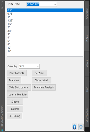 Use the Pipe tab of the Irrigation Palette to work with pipes.
Paint Laterals
Running the Paint Laterals [needs a space on the button] command will change the cursor to a circle that will snap a lateral pipe to any heads or Remote Control Valves that it touches. The flow of any sprinklers painted on the current instance will be added to the sum next to the cursor.
Clicking while the command is active will designate a joint in the pipe, which can be used to add turns or angles to the pipe without needing a sprinkler to join to.
"Paint laterals" will not calculate the flows of existing pipe, even if connected, it's recommended to use the Total Flows command [maybe move total flows here or copy it] instead.
After the command is started, and a point is made (either to an existing sprinkler or designating a point by clicking) pressing V will alter the next input to be a Remote Control Valve, clicking at this point will insert the valve at the cursor, snapping to center on a Mainline pipe if present, rotating to be parallel.
Mainline [should be shown above paint laterals by virtue of it's used first?]
Prompts the user to designate a start point for mainline, clicking will designate another point, but the mainline will not register correctly if connected back to itself in the same instance of the command.
Show Label
Zone sizing labels actual size changes between neighboring pipes. Label Smallest Pipe controls whether the default (minimum) size is labeled at those changes. The source pipe is also labeled when it is larger than the default size.
Label End Pipes adds labels to terminal pipes, including minimum-size pipes. Turn it off to omit labels added only because a pipe is at the end. A terminal pipe can still receive a size-change label when its size differs from the adjoining pipe, subject to Label Smallest Pipe.
For example, with a minimum size below 1 inch, a route sized 1½ inch → 1 inch → 1 inch keeps labels on the first two pipes at the size change. The final 1-inch pipe gets an end label only when Label End Pipes is on.
After changing either setting, run zone sizing again to replace the zone's automatic labels. Repeated sizing removes obsolete labels and preserves required labels on shared sections without duplicates.
Use Show Label to add another size label manually, such as near a match line.
Hydraulic analysis and fitting allowance
In Settings, open the hydraulic calculations page and set Fitting Allowance (%). This value is saved with the drawing and applies to both mainline and lateral pipe friction in hydraulic analysis and pipe sizing. The default is 10%; enter 0% to disable the allowance. Drawings without a saved value start at 10%.
To reproduce the calculation, multiply pipe friction by 1 + allowance / 100. For example, 4 PSI of pipe friction with a 10% allowance becomes 4.4 PSI, including 0.4 PSI for fittings. Elevation changes, valve pressure losses, and pump gains are calculated separately. The allowance does not change physical pipe lengths or material quantities. Analysis summaries show the selected percentage and identify friction totals as including fittings.
Find Critical Zone evaluates each candidate zone independently. Run Scenario evaluates the checked zones together. With the same single zone selected and unchanged drawing inputs, both use the same demands and fitting allowance. Previously running zones do not add hidden demand; intentionally placed non-zone demands remain included. After a successful analysis, the palette remembers the resulting running-zone selection.
Mainline pipes on both sides of a zone takeoff connect to the zone valve inlet, regardless of pipe drawing direction. Only that zone's lateral pipes connect to its outlet. This keeps loop flow from bypassing the valve pressure loss.
In the hydraulic summary, Required Pressure at POC totals required RCV pressure plus mainline friction, elevation and inline valve losses, matching the Excel report. Booster gain is listed separately. Residual Pressure = Available Pressure at POC + Booster Gain - Required Pressure at POC.
The Zones table compares Required and Modeled pressures at each running control valve inlet. Required pressure includes the valve and lateral losses needed to satisfy the zone's most pressure-limited demand. Residual = Modeled - Required. These analysis values are available even before separate zone sizing and do not overwrite saved sizing inputs. Run Scenario clears results for zones that are not running.